

Resistance Soldering
This talk on resistance soldering was presented by John de la Lande to the 5th Narrow Gauge Convention held in Melbourne 14/15th April 2001 and updated as new solders and fluxes have become available.
Unfortunately there is no Resistance Soldering equipment available from Brunel Hobbies or any other source in Australia (as of September 2015). An American company "American Beauty" does manufacture a unit for 240V but it has to be ordered online directly from them. Note that their RSU is not certified for use in Australia.
Introduction
This soldering technique has come into prominence over the last few years although it has been used in the jewellery business for 20 years or more.
There has been much written in the modelling press and elsewhere about resistance soldering. In spite of this however, there still seems to be a large number of misconceptions about the method, not only amongst the average modeller, but even by exponents of the technique. These are often centred around a lack of understanding about why and how it works and to limitations in the equipment used. Hopefully these notes will in some way help rectify these misunderstandings.
Theory
Resistance soldering as the name suggests relies on the resistance of the solder to the flow of an electric current to generate enough heat to melt the solder. This occurs in exactly the same way as an electric radiator or incandescent light bulb works. In the case of the radiator, only the radiator bar becomes red-hot and not the plug, electric lead, the switch or the connections in the radiator. How is this managed? In simple terms what is done is to provide a very easy or low resistance path for the current (ie electrons) to flow from the power point to the radiator bar. The radiator bar itself however is made of wire that is more difficult for the current to flow through (ie it offers more resistance to the flow of electrons) and in so doing it generates heat. In a sense the friction between the electrons and the material it is passing through generates the heat. An easy path is then provided for the electrons to return to the power point from the other end of the bar. For the purists out there I am ignoring the fact that power from the mains is alternating current (or AC) as the theory is still the same.
How do you make an easy path for the current to flow through? This is determined simply by the thickness (actually cross sectional area) and the type of material (usually metal) the current is to flow through. The thicker the material, the easier it is for the current to flow through it, and less heat will be generated. Note also that the connections between the wire, say, and a plug can be critical. If only some of the wire is in contact with the wire connector or if it is dirty or tarnished it can cause the plug to become very hot. All modellers are familiar with this in terms of dirty trackwork or wheel pickups on engines causing running problems.
For those that remember their "high school" physics all this is based on a simple law of electricity called Ohm's Law which states that the voltage is equal to the current flowing through the wire multiplied by its resistance (V = IR). The amount of heat generated by an electric current flowing through a wire (or solder) is determined by the voltage across it and the current flowing through it (W = VI). The heat output is measured in Watts (eg: for example a 1,000 W radiator compared to a 1,500 W radiator).
The Equipment
Enough of theory! How does this work in practice? Well clearly what is required is a source of electric current, some method of being able to control the flow of the current, and some way of making it pass through the solder to make the joint.
The electric current is generally supplied by a transformer, which lowers the mains voltage (240V) to an acceptable safe voltage of a few volts only. At this voltage large currents (of the order of 10s of Amps) are required to melt the solder so it should be capable of supplying currents of up to 50 Amps or more.
Controlling the current flow is tricky and absolutely essential. Passing a large current through a small object you are trying to solder (such as a lamp iron) could simply evaporate it! In most units this is done by providing multiple voltage taps or plugs on the transformer. The modeller can then select a lower voltage to lower the current flow and hence the amount of heat generated. The problem with this method is that the steps are somewhat coarse and this limits the use of the unit particularly for small soldering jobs and makes soldering of white metal almost impossible. The unit I use allows the current to be varied continuously from next to nothing to many amps.
Some method of providing a path for the current to flow through the solder needs to be provided. This is normally done by providing a lead with an alligator clip on the end to connect directly to one of the items to be joined (normally the larger one such as a coach side) and a copper sheathed carbon probe to touch close to the joint to be made on the other item. The carbon probe is used as it will not react with the metal or solder or scratch items to be joined and can be "sharpened" easily.
The resistance soldering equipment I use is shown in Fig 1.
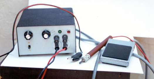
Figure 1: The Resistance Soldering Unit
This is a "home grown" product, which was developed by Roger Howell ("Bluerink Models") as a result of discussions between Roger and myself about the limitations or equipment available from the UK. It consists of a control box (full of electronics!) shown on the left of the photo; a foot switch on the right; and between them an alligator clip and a probe. The alligator clip and the probe are connected by heavy wires (for low resistance) to the two outlets on the control box. The foot switch (controlling a low voltage circuit) is used to switch the current on and off for soldering (thus freeing up your hands -most essential). The controls consist of an off-on knob combined with a time switch (top left of controller): a switch to switch on timer (bottom left); a knob to control amount of current (top middle); a power on light (top right); a soldering current on light (top towards centre from right); and two pairs of plugs for soldering leads. The timer is a useful addition and allows multiple items of the same type to be soldered consistently without worrying about timing each time. You may be able to see some pencilled marks beside the current control knob - these indicate settings for white metal, small brass objects and door hinges!
A picture of the probe is shown in Fig 2 while an exploded view of the same probe is shown in Fig 3. The handle is from Exactoscale as is the carbon rod while the metal holder is a coaxial coaxial TV antenna connector adapted as a collett. The brass insert to which the lead is soldered was made by myself.
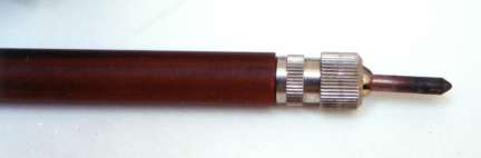
Figure 2: Close-up view of the soldering probe.
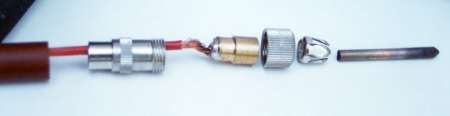
Figure 3: Exploded view of the soldering probe.
Techniques
Before proceeding I need to emphasise that the components of brass, or whatever, that are to be soldered together must be cleaned and prepared in the same way as for "normal" soldering. If this is not done than your soldered joins may be less than adequate and can even fall apart. Also it may substantially increase the current required to make the joint and possibly damage the components.
I use a metal plate, metal blocks and strips and various magnets (Fig 4) to act as a jig to hold the components in place while I solder them. Fig 5 shows my resistance soldering unit in use. It is being used to solder a brass strip to a plate of brass. The alligator clip is clipped to the brass plate whole the probe is placed just above the joint. Both pieces were tinned.
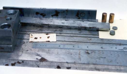
Figure 4: Metal plate, bars, magnets used for resistance soldering.
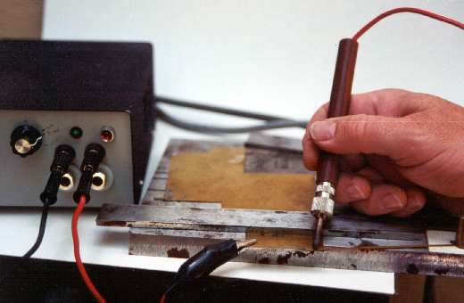
Figure 5: The reistance soldering unit in use.
To illustrate the use of resistance soldering I will concentrate on three aspects of coach building and the construction of a crossing vee for the Broad Gauge. The aspects of coach building are the construction of the body shell, soldering the window droplights in position, and widening the compensation system for the GWR Broad Gauge. Resistance soldering is particularly useful for this type of kit bashing where alignment and tolerances of "fiddly" small pieces of brass are critical.
The Body Shell
Form the body sides and ends as per the kit instructions or the prototype and tin the ends that are to be joined (see Fig 6). Brunel Models 145C solder and Number One Flux is recommended for this purpose.
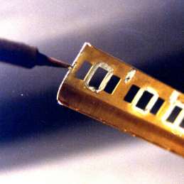
Figure 6: Tinning the ends of the coach side.
Do not use too much solder - it should be a thin uniform coat. Next set one of the coach sides and end in the jig as shown in Fig 7. Alignment of the end and side can be precisely controlled using the metal blocks and magnets. You also need to insulate either the end or the side from the metal slab and the blocks. In this case the end has been insulated.
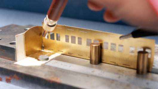
Figure 7: The coach side and end held by magnets and blocks on the metal plate. Note the cardboard used to insulate the end from the metal plate and blocks.
This has two purposes, firstly to electrically separate the coach end from the coach side and thereby make sure that all the current flows through the joint that is to be soldered, and secondly to allow maximum heating of the block. In Fig 7 one lead from the resistance soldering unit has been clipped to the top of the coach on the right of the picture while the probe is held touching the end as close to the coach side as possible. To facilitate current flow across the joint Brunel Models No: 1 Flux can be brushed onto it. To avoid heat distortion place the probe in the middle of the joint to be made (as shown) and apply current until the solder melts. Then move the probe to the top of the join and do the same again. Repeat this at the bottom of the joint then between each of these points successively until the entire joint is soldered. This will produce a very clean joint both inside and outside the coach and should require very little cleaning up.
If a stronger joint is required follow the same procedure and then use a pair of tweezers to just hold a piece of solder on the inside of the coach joint. Touch the resistance soldering unit's probe to the piece of solder and apply the current. It will quickly melt the solder, which will run up and down the joint. You can move the probe as the current is applied to facilitate this. Repeat this procedure as necessary. You can also use some of the new "no clean" and "no residue" solder paste for the same purpose.
Droplights
Resistance soldering is particularly good for soldering droplights in position. With normal soldering techniques these are fiddly and difficult to solder exactly in place while resistance soldering makes the task easy and fast.
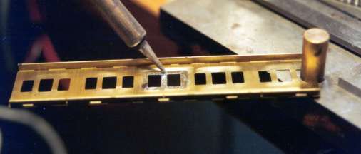
Figure 8: Tinning the window surrounds.
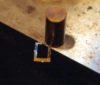
Figure 9: Tinning the droplight.
First tin the droplight and the window surrounds (Figs 8 & 9). Although a solder paste was available that could have been used for tinning it was not satisfactory as it had a tendency to splatter and require more cleaning up. However, a new product is now available from Brunel Models that contains a solder and flux in a syringe that is "no clean" and "no residue" that is well suited to this purpose (see Soldering Made Easy Part 1). Next place the droplight tinned side up on a metal bar. The width of the bar should be no more than 2/3 the height of the coach side otherwise any tumblehome may cause problems. Next cut a hole in a Post-It note and place it as shown in Fig 10 with the droplight centred on the hole. I use Post-It notes as the sticky edge holds it in place quite well.
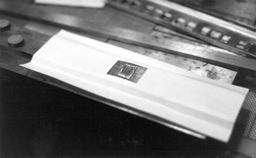
Figure 10: The use of the Post-it Note.
The Post-It note acts as an electrical insulator between the coach side and the metal strip. Next place the coach side over the droplight so that it lines up precisely behind the window to which it is to be soldered (see Fig 11).
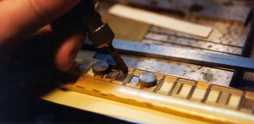
Figure 11: The droplight being soldered into position.
Clamp the coach side firmly in place using magnets as shown. Attach the alligator clip lead from the resistance soldering unit to the metal strip (or the underlying metal slab) and using the probe solder the droplight in place so that it is held securely. Do not attempt to solder it firmly in place at this stage. Now turn the coach side over and finish soldering the droplight in place from the inside of the coach (see Fig 12).
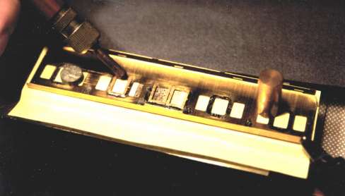
Figure 12: Completeing the soldering of the droplight in place from the inside of the coach.
Why not finish soldering the droplight in place from the outside of the coach rather than turning it over and soldering from the inside? This is to minimise damage in terms of pitting and discolouring to the window surrounds. As there is often considerable detail etched into the coach side around a window it can be damaged by the current passing through it as the carbon tip on the probe may not make perfect contact with the brass. By finishing soldering from the rear you eliminate this possibility and can use a larger current if you wish.
Note that to avoid distortion and overheating never solder at one point and then at a point just beside the first point. In this case the soldering order should be "top", then "bottom", "left side", "right side" and then in the same order half way between each of the points and so on. It's a bit like tightening the nuts that hold a car wheel on - never tighten an adjacent one - always move to the opposite one. Remember resistance soldering can generate just as much or more heat in a joint and the surrounding metal as a normal soldering iron can. It is just more easily controlled and localised.
This case also illustrates the importance of understanding how resistance soldering works and the importance of making sure the electrical current flows through the joint to be made and is not diverted elsewhere of "shorted out". The Post-It note used here makes sure the current flows through the coach side via the joint to be made with the droplight.
Compensation Modifications
The widening of the compensation system required that I had to cut the "W" irons away from the compensation plate as supplied in the kit. I did this leaving just enough brass to act as a flange to enable "T" section brass lengths to be used to space "W" irons correctly for the new gauge. The problem was to hold the "T" section brass length exactly as required and solder them at the same time. Fig 13 illustrates the solution to the problem.
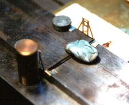
Figure 13: Holding and insulating components (1).
Using the metal strips and magnets the "W" irons are held at exactly the same distance apart and parallel to each other while the "T" section brass was held parallel to each other while the "T" section brass was held in place by Blue Tack. (Blue Tack is particularly useful for holding components in place for resistance soldering. It can get hot and sticky but let it cool down before removing it and it will come off quite easily without leaving a residue.) The alligator clip lead was then attached to the metal strip and the strip and the probe used to solder the "T" section brass in place. No insulation was used between the flanges and the metal strip as only a small joint was required to be made.
The rest of the original compensation system was then soldered back in place onto the "T" section brass. This was done as shown in Fig 14 the joints were tinned as usual and the probe used to solder them in place by touching it to the original compensation etch NOT the "T" section brass. The current flow was from the original compensation etch through the joint to be made to the "T" section brass. The piece of Post-It note under the original compensation etch is to insulate it from the underlying metal strip to which the rest of the components are in contact.
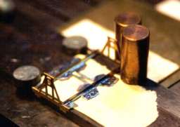
Figure 14: Holding and insulating components (2).
Crossing Vee
Broad Gauge track was laid on "baulks" (lengths of timber) rather than sleepers. The crossing vee for model purposes is best constructed on a piece of copper clad board and the track soldered to the board. High accuracy is obviously required. I initially tin the rail base and the copper clad board and then clamp the copper clad board into a vice, attach the alligator clip lead to the copper clad board, and using blue tack and a check rail gauge solder the vee to the board using the probe (see Fig 15).
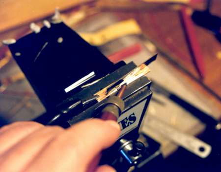
Figure 15: Using a vice to solder a crossing Vee.
Summing Up
- Parts to be soldered must be cleaned as you would for normal soldering.
- Apply the probe to the component before applying the current (via the footswitch).
- Start with a low current first then increase the current if necessary.
- Stop the current (using footswitch) before lifting the probe from the component.
- If joining tinned components use a flux, such as Carr's Red Label, to initially facilitate the current flow and produce a solid joint.
- If using solder paste use it sparingly to reduce splatter.
- Always connect the alligator clip to the larger component or clamp it to the metal plate using magnets (to which the alligator clip is connected).